User Kasumiikun_ uploaded the image
A black and white diagram that shows a circuit diagram of a source level control system. The diagram is divided into four sections, each representing a different component of the system. The first section is labeled "Source level control" and shows a series of rectangular boxes connected by lines. The boxes are arranged in a grid-like pattern, with each box representing a component. The first box is labeled as "DUT" and has a label that reads "To-do list". The second box is labelled as "To do list" and contains a label with a description of the component. In the third section, there are two rectangular boxes, one labeled "Dut" and the other labeled as DUT. The fourth box has a rectangular box with a label on it, and the fifth box has an image of a circuit board with a voltage regulator. The circuit board has two resistors, one on each side, and one on the other side.
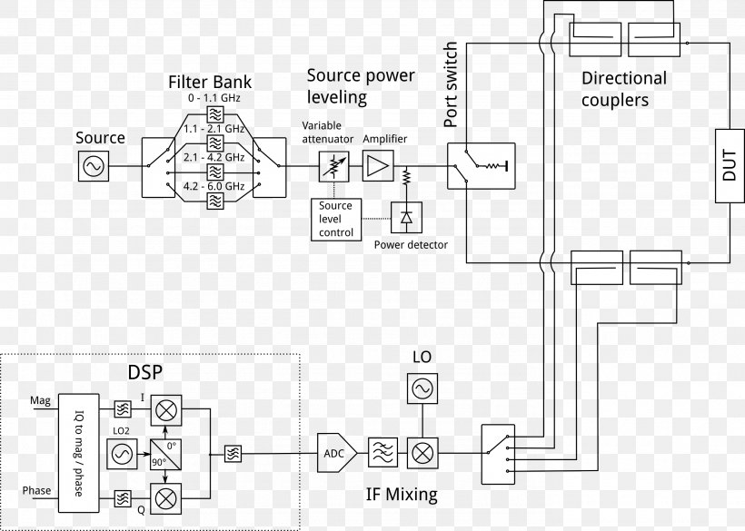
Floor Plan Block Diagram Network Analyzer Wiring Diagram Circuit Diagram PNG
. The resolution of this PNG file is 2761 x 1972 pixels and it has a file size of 219.27 KB.A black and white diagram that shows a circuit diagram of a source level control system. The diagram is divided into four sections, each representing a different component of the system. The first section is labeled "Source level control" and shows a series of rectangular boxes connected by lines. The boxes are arranged in a grid-like pattern, with each box representing a component. The first box is labeled as "DUT" and has a label that reads "To-do list". The second box is labelled as "To do list" and contains a label with a description of the component. In the third section, there are two rectangular boxes, one labeled "Dut" and the other labeled as DUT. The fourth box has a rectangular box with a label on it, and the fifth box has an image of a circuit board with a voltage regulator. The circuit board has two resistors, one on each side, and one on the other side.
Floor Plan Block Diagram Network Analyzer Wiring Diagram Circuit Diagram PNG
Related PNG Images