User kurooissohotwtf uploaded the image
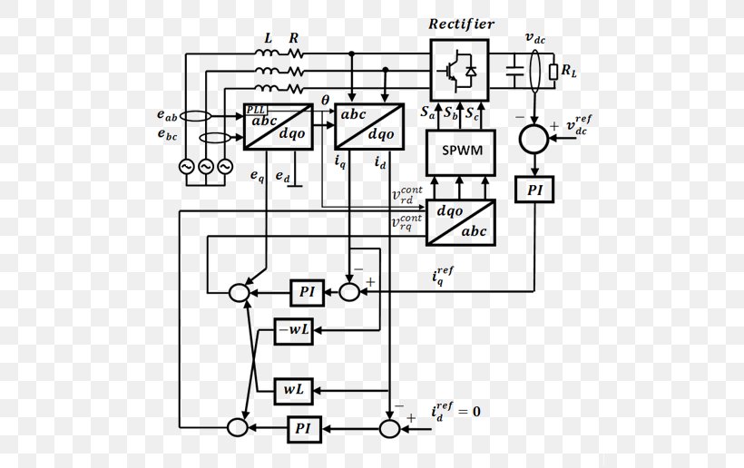
A circuit diagram of a rectifier, which is a type of electronic device used to control the flow of electricity in a circuit. The circuit consists of several components such as resistors, capacitors, transistors, and diodes. The rectifier is connected to a DC motor, which powers the rectifier. The rectifier has a rectangular shape with a rectangular base and a rectangular top. The diode is located in the center of the circuit, and the diode and diode are connected to the rectifiers. There are also several resistors and capacitors connected to it, which are used to regulate the voltage and current in the circuit. These resistors are also used in the rectification process, such as capacitors and transistors. The capacitors are also connected to rectifiers, which help to regulate their current and voltage levels. - L, R, and L, are the components that make up the circuit and how they interact with each other. The DC motor is responsible for controlling the voltage, which can be seen in the diagram. The resistor is also used to convert the voltage from DC to DC, which helps to reduce the current and increase the voltage in the DC motor. – P1, P2, P3, P4, P5, P6, P7, P8, P9, P10, P11, P12, P13, P14, P15, P16, P17, P18, P19, P20, P21, P22, P23, P24, P25, P26, P27, P28, P29, P30, P31, P32, P33, P34, P35, P36, P37, P38, P39, P40, P41, P42, P43, P44, P45, P46, P47, P48, P50, P51, P52, P53, P54, P55, P56, P57, P58, P60, P61, P62, P63, P64, P65, P66, P67, P68, P69, P70, P80, P71, P82, P83, P84, P85, P86, P87, P88, P90, P91, P92, P93, P.
Design Electrical Network Floor Plan Engineering Electrical Grid PNG
. The resolution of this PNG file is 521 x 516 pixels and it has a file size of 174.13 KB.A circuit diagram of a rectifier, which is a type of electronic device used to control the flow of electricity in a circuit. The circuit consists of several components such as resistors, capacitors, transistors, and diodes. The rectifier is connected to a DC motor, which powers the rectifier. The rectifier has a rectangular shape with a rectangular base and a rectangular top. The diode is located in the center of the circuit, and the diode and diode are connected to the rectifiers. There are also several resistors and capacitors connected to it, which are used to regulate the voltage and current in the circuit. These resistors are also used in the rectification process, such as capacitors and transistors. The capacitors are also connected to rectifiers, which help to regulate their current and voltage levels. - L, R, and L, are the components that make up the circuit and how they interact with each other. The DC motor is responsible for controlling the voltage, which can be seen in the diagram. The resistor is also used to convert the voltage from DC to DC, which helps to reduce the current and increase the voltage in the DC motor. – P1, P2, P3, P4, P5, P6, P7, P8, P9, P10, P11, P12, P13, P14, P15, P16, P17, P18, P19, P20, P21, P22, P23, P24, P25, P26, P27, P28, P29, P30, P31, P32, P33, P34, P35, P36, P37, P38, P39, P40, P41, P42, P43, P44, P45, P46, P47, P48, P50, P51, P52, P53, P54, P55, P56, P57, P58, P60, P61, P62, P63, P64, P65, P66, P67, P68, P69, P70, P80, P71, P82, P83, P84, P85, P86, P87, P88, P90, P91, P92, P93, P.
Design Electrical Network Floor Plan Engineering Electrical Grid PNG
Related PNG Images