User myrticewota62 uploaded the image
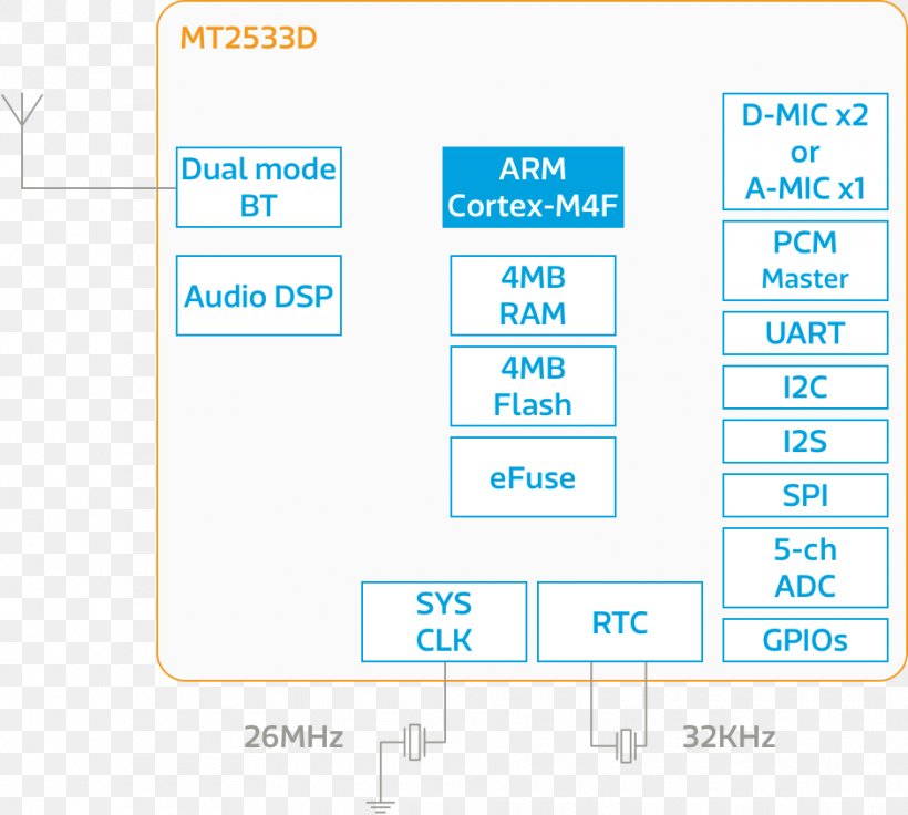
A block diagram of a dual-mode audio DSP (Dual mode BT) and ARM Cortex-M4F (ARM Cortex M4F) processor. The block diagram shows the different components of the processor, including the dual mode BT, dual mode RT, 4MB RAM, RAM Flash, Efuse, and 5-ch ADC (ADC) processor, as well as the PCI Master (PCM Master) and UART (UART) processors. The block diagram is labeled with the names of the components and their connections. The dual mode Bt is represented by a blue rectangular box with the text "Dual mode RT" and "Audio DSP" written on it. The Audio DSP is shown in the top left corner of the block diagram, while the Dual mode RT is shown on the top right corner. There are also several other components in the diagram, including a D-MIC x2 or A-MIC X1 processor, a PCM Master processor, and a PCI Master processor. These components are connected to each other by a series of wires, which are used to connect them to a computer or other electronic device. The image also shows the 26MHz (26MHz) power supply, which is used to power the processor from 26MHz to 32MHz.
Line Angle Product Organization Font PNG
. The resolution of this PNG file is 940 x 844 pixels and it has a file size of 24.46 KB.A block diagram of a dual-mode audio DSP (Dual mode BT) and ARM Cortex-M4F (ARM Cortex M4F) processor. The block diagram shows the different components of the processor, including the dual mode BT, dual mode RT, 4MB RAM, RAM Flash, Efuse, and 5-ch ADC (ADC) processor, as well as the PCI Master (PCM Master) and UART (UART) processors. The block diagram is labeled with the names of the components and their connections. The dual mode Bt is represented by a blue rectangular box with the text "Dual mode RT" and "Audio DSP" written on it. The Audio DSP is shown in the top left corner of the block diagram, while the Dual mode RT is shown on the top right corner. There are also several other components in the diagram, including a D-MIC x2 or A-MIC X1 processor, a PCM Master processor, and a PCI Master processor. These components are connected to each other by a series of wires, which are used to connect them to a computer or other electronic device. The image also shows the 26MHz (26MHz) power supply, which is used to power the processor from 26MHz to 32MHz.
Related PNG Images