User meidal11 uploaded the image
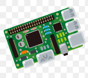
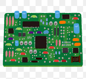
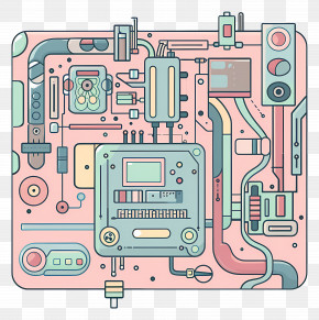
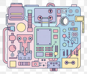
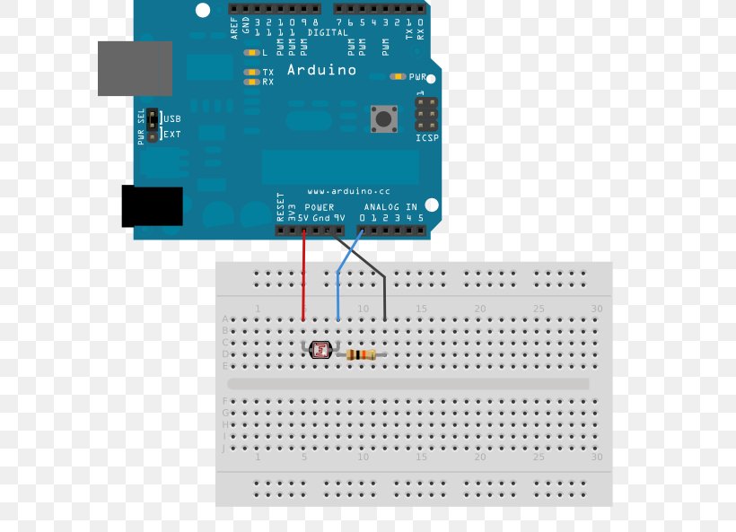
The image shows an Arduino Uno connected to a breadboard. The breadboard has a blue circuit board with various buttons and switches on it. On the left side of the breadboard, there is a USB port and a USB cable connected to it. On the right side, there are two resistors, one red and one yellow, connected to the Arduino board. The red resistor is connected to an ICSP (Input-Output Converter) and the yellow resistor is used to connect it to the ICSP. There is also a power supply on the board, which is used for controlling the output of the Arduino. The output is labeled "www.arduino.co.uk" and there are several capacitors and resistors visible on the circuit board. This is likely used to power the Arduino and other electronic components.
Arduino Electronics Electronic Circuit Sensor Electronic Component PNG
. The resolution of this PNG file is 602 x 593 pixels and it has a file size of 68.97 KB.The image shows an Arduino Uno connected to a breadboard. The breadboard has a blue circuit board with various buttons and switches on it. On the left side of the breadboard, there is a USB port and a USB cable connected to it. On the right side, there are two resistors, one red and one yellow, connected to the Arduino board. The red resistor is connected to an ICSP (Input-Output Converter) and the yellow resistor is used to connect it to the ICSP. There is also a power supply on the board, which is used for controlling the output of the Arduino. The output is labeled "www.arduino.co.uk" and there are several capacitors and resistors visible on the circuit board. This is likely used to power the Arduino and other electronic components.
Arduino Electronics Electronic Circuit Sensor Electronic Component PNG
Related PNG Images